Hip and Valley Roof Angles
Overview of Tetrahedra and Triangles defining a Hip or Valley Roof
Developments of Hip and Valley Roof Angles based on the Roof Lines
Development of Tetrahedron composed of Right Triangles
Slideshow ... Development of Tetrahedron composed of Right Triangles
Compass and Straightedge Solution ... Unequal Roof Slopes with Irregular Plan Angle
Plan Angle Formulas ... Unequal Roof Slopes with Irregular Plan Angle
Hip/Valley Side Cut Angles
Developments of Valley Related Angles (pdf)
Developments of Valley Related Angles (doc)
(R4B , R4P) Developments of Hip-Valley Side Cut Angles
Developments of Hip-Valley Side Cut Angles and related Compound Angles
Applied Hip-Valley Side Cut Angles (pdf)
Slideshows: Developments on the Stick
Saw Blade Bevel for any Compound Angle
(R4B , R4P) Miter Angle on Upper Shoulder of Hip-Valley
(A5B , A5P) Blade Bevel on Upper Shoulder of Hip-Valley
(C1 , P1 , C5, 90 - P2) Purlin related Angles
(C1 , R2 , R3) Square Hung Fascia Angles on the Hip Rafter
Framing Angle Geometry Slideshows
Development of Tetrahedron composed of Right Triangles
(C5) Development of Backing Angle
Tetrahedral Model of Backing Angle
Revolution of the Plane of the Backing Angle
(A7) Hip/Valley Shift and Plumb Backing Angle
(90 - P2) Sheathing Angle Ratio
Compound Angle Tetrahedron compared to Hip Roof Model
Tetrahedral Model of Compound Angle extracted and developed
Housing Chamfer or Shelf Cut extracted from Compound Angle
Images of 3D Models of Hip-Valley Roof Geometry
Interlocking Tetrahedra modeling the Backing Angle
Interlocking Tetrahedra modeling Prow Roof Stud Compound Angle
Interlocking Tetrahedra modeling Housing and Tenon Chamfer Cut (Square Cut) Angles
Tetrahedra modeling Hip Side Cut Angles at Hip Peak and Jack Rafter Side Cut Angles
(R4B , R4P, R5B, R5P) "Post" type models of Hip-Valley Rafter Side Cut Angles
Tetrahedra relating the angles on the upper shoulder of a Hip-Valley Rafter
(P1, P2, R2, Q3) Jack Purlin Miter Angles
Developments of Tetrahedral Models
Developed Tetrahedral Model of Hip Roof
Tetrahedra extracted from a Hip Roof
Developed Tetrahedral Model of Compound Angle
Developments of and exploded views of Tetrahedra modeling a Hip Roof (pdf)
Tetrahedra modeling the Backing Angles (pdf)
Construction of Backing Angle
Backing Angle Model: Regular Octogonal Gazebo
(A7) Tetrahedra modeling the Plumb Backing Angle
(A7) Tetrahedra modeling the Plumb Backing Angle
Hip Rafter Side Cut Angles
Developed Tetrahedron: Jack Rafter Compound Angle
Developed Tetrahedron: Jack Rafter Compound Angle
Developments of Purlin Related Angles (pdf)
(C5 , C1 , P1 , P2 , R2) Developments of Purlin Related Angles
Development of Q3 ... angle formed on Hip Rafter intersected by Purlin
Developed Tetrahedron: Purlin Compound Angle
(P1 , R2 , Q3) Miter Angles related to Jack Purlin
(P1 , C1 , R2) Purlin Angles developed using Reciprocal Roof Pitch
Developments of "Layover" type Rafters and Purlins
Fundamental Angles for "Layover" type Roof ... 90° Ridge Intersection
Developments of Square Hung Fascia Angles
Angled Fascia intersects Hip Rafter square to long axis of Hip
Rake Wall or Prow Peak ... Compound Angle on the Stud or Post
Rake Wall or Prow Peak ... Development of Compound Angle on the Stud or Post
Rake Wall or Prow Peak ... angled Crown or Fascia with equal abutting Compound Angles
Rake Wall or Prow Peak with angled Crown or Fascia ... Compound Angles at Hip Rafter Foot
Studies of Hip Rafter Geometry
Square Hung Fascia intersects foot of unbacked regular Hip Rafter
Developments of tetrahedra extracted from Hip Rafter
Developments of Polyhedra extracted from the Hip Rafter
Tetrahedra extracted from the upper shoulder of the Hip Rafter
Tetrahedra extracted from the upper shoulder of beveled Hip Rafter
Detailed Studies of intersecting Hip-Valley Roof Members
Development of Chamfer or Square Cut Angles on upper shoulders of Jack Purlins and Jack Rafters
Study of Shelf Cut at intersection of Valley Rafter Foot with Principal Common Rafter
Study of Shelf Cut at intersection of Valley Rafter Peak with Principal Purlin
Development of Jack Rafter Chamfer Cut along plumb line intersection with Hip or Valley Rafter
Development of Jack Rafter Chamfer Cut along plumb line intersection with Hip or Valley Rafter
Development of Jack Purlin Chamfer Cut along line of intersection with Hip or Valley Rafter
Development of Jack Purlin Chamfer Cut along line of intersection with Hip or Valley Rafter
Development of Jack Purlin Shelf Cut following line parallel to long axis of the Hip or Valley Rafter
Development of Jack Rafter Shelf Cut following line parallel to long axis of the Hip or Valley Rafter
3D Models of Mortises and Tenons
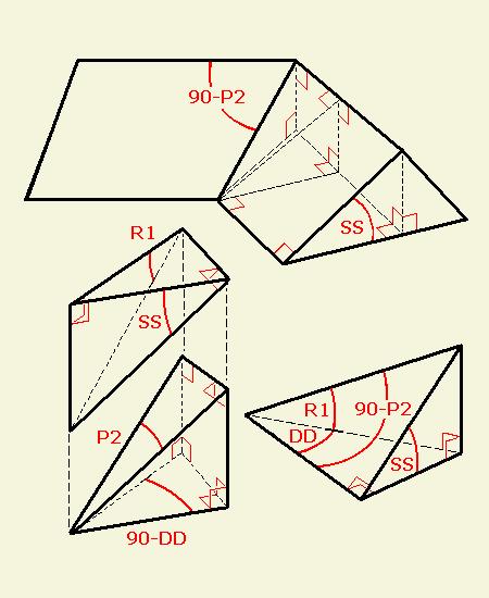
The first development below models a section of a Hip roof, with Deck angle DD on a level plane passing through the eaves, and the angle on the plane of the roof 90 - P2 located at the Hip eave or base. The same development serves for a Valley rafter, but the deck is defined as a level plane passing through the ridges, therefore DD and 90 - P2 are located at the Valley ridge or peak. The R4 angles also follow this pattern: R4B angles are projections of DD and D at the Hip rafter eave or Valley rafter ridge. R4P angles are projections of 90 - DD and 90 - D at the Hip rafter peak or Valley rafter foot. |
|
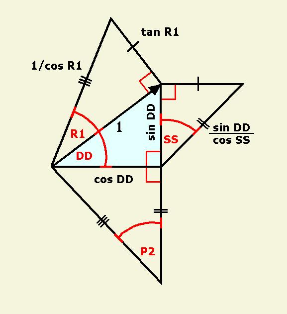
Development of Main Side Angles:
Common Pitch angle = SS Hip Pitch angle = R1 Deck angle = DD Angle on the Roof Plane = P2 The unit length for the Hip run and the trigonometric lengths given for the line segments on the drawings may be disregarded. The developments may be drawn to any scale, using only a straightedge and a compass for the line segments marked equal. Substitute angles S for SS, and D for DD, to develop the Adjacent side angles. |
|
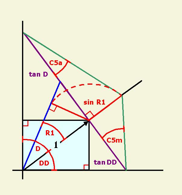
Development of Backing Angles (C5):
W = DD + D, where 0 < W < 180 degrees Produce the lines defining the Hip eaves or Valley ridges Construct the triangle of Hip Pitch angle R1 Construct line segment sin R1 Rotate line segment sin R1 to the line of the Hip run produced Construct the line segments tan DD and tan D perpendicular to the Hip run Draw the line segments (hypotenuse) for C5 angles tan C5m = sin R1 ÷ tan DD tan C5a = sin R1 ÷ tan D |
|
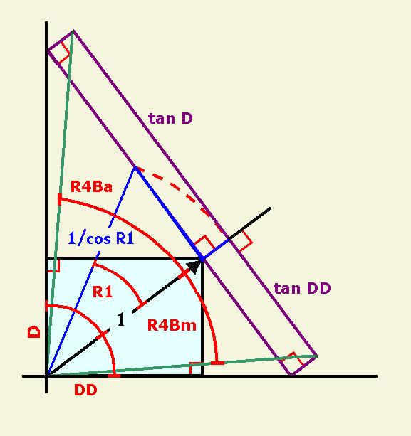
Development of Angles on the Bottom Face of the Valley
at the Hip Eaves, or Valley Ridges (R4B): W = DD + D, where 0 < W < 180 degrees Produce the lines defining the Hip eaves or Valley ridges Construct the triangle of Hip Pitch angle R1 Rotate line segment 1/cos R1 to the Hip run Construct the line segments tan DD and tan D perpendicular to the Hip run Construct the parallel line segments tan DD and tan D perpendicular to the Hip run produced to 1/cos R1 Draw the line segments (hypotenuse) for R4B angles tan R4Bm = tan DD / (1/cos R1) = cos R1 tan DD tan R4Ba = tan D / (1/cos R1) = cos R1 tan D |
|
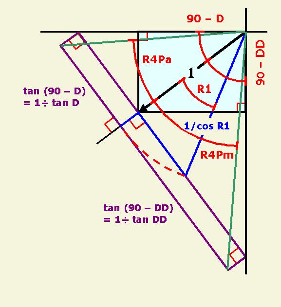
Development of Angles on the Bottom Face of the Valley
at the Hip Peaks, or Valley Feet (R4P): W = DD + D, where 0 < W < 180 degrees Produce the lines defining 180 - W = 90 - DD + 90 - D Construct the triangle of Hip Pitch angle R1 Rotate line segment 1/cos R1 to the Hip run Construct the line segments tan (90 - DD) and tan (90 - D) perpendicular to the Hip run Construct the parallel line segments tan (90 - DD) and tan (90 - D) perpendicular to the Hip run produced to 1/cos R1 Draw the line segments (hypotenuse) for R4P angles tan R4Pm = (1/tan DD) / (1/cos R1) = cos R1 / tan DD tan R4Pa = (1/tan D) / (1/cos R1) = cos R1 / tan D |
|
Formulas for Hip/Valley Joinery at Eaves and Ridges:
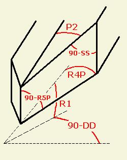
The dihedral angle, or angle between two planes, where the bottom face of a Hip or Valley rafter intercepts plumb planes passing through the eaves or ridges, is defined as angle 90 + A5 or 90 - A5. Therefore, the saw blade angle setting along Miter line R4 on the Valley, or along a line following R5 on a plumb face, is A5. The Bevel line on the plumb Valley face is 90 - R1. tan Blade angle = sin Miter / tan Bevel tan A5B = sin R4B / tan (90 - R1) = sin R4B tan R1 tan A5P = sin R4P / tan (90 - R1) = sin R4P tan R1 Angles 90 + R5 and 90 - R5 are created on the cross section of the Valley rafter by cutting the compound angle. cos Angle on Compound Face = cos Miter cos Bevel cos (90 - R5B) = cos R4B cos (90 - R1) sin R5B = cos R4B sin R1 cos (90 - R5P) = cos R4P cos (90 - R1) sin R5P = cos R4P sin R1 |
|
Valley rafter foot meets plumb planes at walls, showing the major planes and angles.
|
HOME PAGE