|
For a compound joint to be possible the shape or profile in cross section must be symmetrical about its centerline.
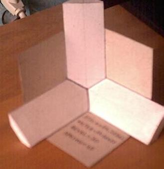
The corners are mutually perpendicular. A section comprised of edges of equal length is extracted from the corner. |
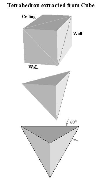
| The compound joint is analysed as three Hip rafters of equal length. The edges of the cube form the ridge lines of the Hip rafters backed at 45°. |
| Cross section view of the molding superimposed on the theoretical Hip rafter model: both pieces are governed by the same geometry. |
| Underside view of the molding detailing the miter and bevel angles. The miter line and bevel angles are the same as required to cut the Hip rafter from its bottom shoulder. |
|
Hip Pitch Angle
= arctan ( tan Common Pitch Angle × sin Plan Angle ) = arctan ( tan 54.73561° × sin 30° ) = 35.26439° Hip Side Cut Angle = Molding Saw Miter Angle = arctan ( cos Hip Pitch Angle ÷ tan Plan Angle ) = arctan ( cos 35.26439° ÷ tan 30° ) = 54.73561° Saw Blade Bevel Angle along Hip Side Cut Angle = Molding Saw Blade Bevel Angle = arctan ( sin Hip Side Cut Angle × tan Hip Pitch Angle ) = arctan ( sin 54.73561° × tan 35.26439° ) = 30° |
| If a miter box is used to cut the compound angle the miter line remains as per the diagram above. The angle required on the adjacent face of the miter box to produce the correct dihedral angle (90° ± Saw Blade Bevel Angle) between the adjoining faces of the molding is 35.26439°, the Hip Pitch Angle. |
Click on the link below to learn more about the
Mathematics of Compound Joints