
Measuring Pinholes with a scanner
By Guillermo Peñate Sep/12/2000
Pinhole photography is not an exact "science" or practice, for that matter and there are many reasons for that, let me mention some of them: the usually long exposures associated with its practice due to the small apertures, the need to apply reciprocity corrections for when exposures are 1 second or longer (very frequently) and last but certainly not least, the difficulty in measuring pinhole diameters, which causes the f/stop to be unknown and ultimately forces us to guess the exposure time, based on -hopefully- familiarity with the camera and a good "eye" to evaluate the existing light conditions.
Some of us, neither have good "eye" nor shoot so frequently to get very familiar with a pinhole camera or just have not been blessed with the capability for determining exposure times without knowing the f/stop of our pinhole camera and the use of a light meter or "sunny/16" rule.
Whatever is the case, to measure pinhole diameters you need a very high magnification optical device and that device should also have measuring capabilities. There are many places you can acquire such devices from, Edmund Scientific is one of them. There are alternative ways to indirectly measure the diameter and most of them are based on projecting the pinhole with an enlarger or a slide projector and finding the actual size by comparative measurements. Today it occurred to me that a flat bed scanner and also film scanners, can be used to measure very small apertures. I successfully measured with my UMAX Astra 2100U scanner 600x1200 DPI ($60 US at Future Shop stores in Toronto, Canada) a pinhole known to be 0.012" in diameter, here is what I did:
- I scanned the pinhole using the highest optical resolution of the scanner 1200 DPI (I know you can argue that a scanner 600x1200 has 600 as the maximum resolution, but let's forget about that). Using my favorite graphic application (Photoshop) I enlarged the image of the pinhole as much as I could, but making sure the edge of the hole was relatively well defined. I found that 200% of the scanned image was as far as I could enlarge the image before the edge was so pixelated that I could not determine where the edge of the hole was. The following are images of that 200% enlargement of the scanned pinhole at 1200 DPI, the one at the right side is the negative version, which for some reason it seems to be easier to measure on the screen than the positive one:


UPDATE (06/01/2003): Once you have your pinhole scanned, you have 2 options, if you have a graphic program capable of measuring distances (Photoshop, for instance) you can use it to measure the diameter of the pinhole you have scanned directly on the screen. In this case it is giving me 0.012" as the diameter of my scanned pinhole.
If you do not own a graphic application capable of measuring, keep on reading.
- I then took a transparent ruler
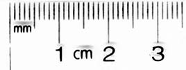 and using the same resolution of 1200 DPI I used for the pinhole, I scanned it and "zoomed in" the image to the same percentage I did for the pinhole, that is 200%. This is a portion corresponding to 5 millimeters of the ruler:
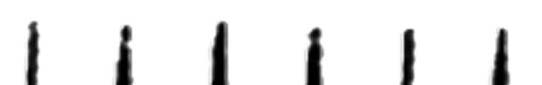
- I measured the pinhole diameter in #1 as seen in the computer screen and obtained 9 millimeters, I will call this distance "D". I also measured the screen distance corresponding to 5 millimeters of the ruler as displayed on the monitor and obtained 149 millimeters, let's call this distance "R" and the 5 millimeters "R" equates to on the actual ruler, distance "A". Therefore: D= 9 mm, R= 148 mm and A= 5 mm (your results will most likely be different, they are based on your monitor size and its width/height adjustment). As practice, I will suggest you take a metric ruler and find the values of D, R of the above 2 images (pinhole and ruler) and then apply the formula in #4 and compare your results.
- Knowing the values of D: pinhole diameter as seen on the monitor, R: distance of 5mm ruler marks as seen on the monitor and A= 5mm, we find the actual size of the pinhole diameter by the following formula:
Diameter of pinhole = A * D / R
substituting the values I found for A, D and R in the above formula, I obtained:
Diameter of pinhole = 5 * 9 / 148 = 0.3040 millimeters
To convert millimeters to inches we divide the millimeters by 25.4
Diameter of pinhole = 0.3040 mm = 0.3040 / 25.4 inches = 0.012 inches (aprox)
I want to mention that the value "A" is chosen arbitrarily, but the larger it is the more accurate your measurement will be. If you did your own measurements on your own monitor and if you did the math, you should have gotten a very similar result of 0.3040mm or 0.012" as the actual diameter of the pinhole, if that is not the case, check your calculations and let me know if you have any question.
At this point you know the diameter of your pinhole and are ready to find the f/stop of your camera. If you need any help finding that (f/stop) as well as help with translating your light meter indicated exposure to your pinhole camera exposure, I invite you to read another small article I wrote on that topic. Click Here to jump to it.
Hope this can help you in your pinhole practice.
Guillermo Peñate
For comments, corrections, questions and suggestions, please contact the author.
Pinholes, Zone Plates, Photon and Pinhole Sieves for SALE!!
Pinhole images: http://ca.oocities.com/penate@rogers.com/guillermo.html
Zone Plate images: http://ca.oocities.com/penate@rogers.com/ZP120.html
Zone Plate article: http://ca.oocities.com/penate@rogers.com/zoneplate.html
Pinhole size and exposure article: http://ca.oocities.com/penate@rogers.com/pinsize.htm
How to measure Pinholes article: http://ca.oocities.com/penate@rogers.com/diameter.htm
Photon Sieve article PDF: http://ca.oocities.com/penate@rogers.com/sieve/photonsieve.pdf
Photon Sieve article HTML: http://ca.oocities.com/penate@rogers.com/sieve/photonsieve.html
Sieve images compared: http://ca.oocities.com/penate@rogers.com/sieve/comparison.html